Cisco ACI seamlessly integrates into virtual environments. The Cisco ACI VMM Integration, also known as ACI Virtualization, provides simplicity without compromising scale, performance, security, or visibility. With Cisco ACI, you can use a unified policy-based model across both physical and virtual environments.
In this article, we will learn how Cisco APIC integrates with the VMware vSphere Distribution Switch (vDS) to extend the benefits of Cisco ACI to the VMware virtualized infrastructure. Unlike other resources, this article assumes you know nothing about Server Virtualization.
- Server Virtualization Overview
- Cisco ACI Virtualization Overview
- Cisco ACI VMM Integration with VMware vDS Overview
- Cisco ACI VMM Integration with VMware vDS Configuration
- Step 1: Deploy the Access Policies for the Host-Connected Interfaces
- Step 2: Create the vCenter VMM domain
- Step 3: Confirm the vDS Creation in the vCenter
- Step 4: Add the ESXi Hosts to the vDS
- Step 5: Assign the VMM domain to the EPGs
- Step 6: Confirm the Port-Group Creation in the vDS
- Step 7: Assign the VM vNIC to the Port Group
- Step 8: Confirm the VM Reachability and Endpoint Learning
- Summary
- Looking for Comprehensive Cisco Data Center Training?
Server Virtualization Overview
Server virtualization is used to mask server resources from server users. Let’s cover the server virtualization basics before digging deep into ACI VMM integration.
What is Server Virtualization?
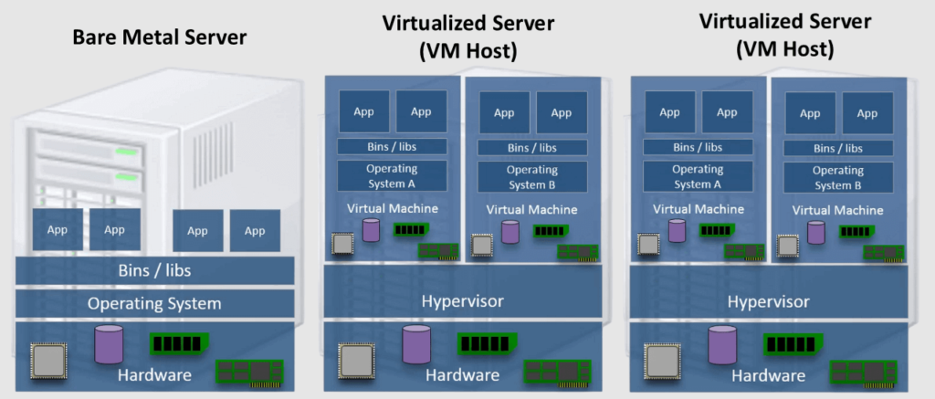
Server virtualization is the process of splitting a physical server into several distinct and isolated virtual servers using software called a hypervisor. Each virtual server can operate its own operating system independently.
The figure below shows that the hypervisor splits the host (server) hardware resources between the hosted virtual machines (VMs).
Why Server Virtualization?
Server virtualization is a cost-effective solution for web hosting and maximizes the use of existing IT resources. Without server virtualization, servers only utilize a fraction of their processing power, leading to idle servers as the workload is spread unevenly across the network. This results in overcrowded data centers with underutilized servers, wasting resources and power. The following summarizes the key benefits of server virtualization:
- Higher server ability.
- Cheaper operating costs.
- Eliminate server complexity.
- Increased application performance.
- Workload Mobility.
What is a Hypervisor?
A hypervisor, also called a virtual machine monitor, is software that enables the creation and operation of virtual machines (VMs). It allows a single host computer to support multiple guest VMs by sharing resources like memory and processing power.
Hypervisors allow better utilization of a system’s resources and enhance IT mobility since guest VMs operate independently of the host hardware. This enables easy migration of VMs between different servers. By running multiple virtual machines on a single physical server, hypervisors reduce the need for space, energy, and maintenance.
In VMware terms, the VMware hypervisor used in the VMware vSphere Distributed Switch (vDS) is called VMware ESXi.
What is a Virtual Switch?
A virtual switch (vSwitch) is a software-based switch that enables communication between virtual machines (VMs) and between VMs and the physical network.
A vSwitch works similarly to a physical network switch but operates entirely within the virtual environment. It connects VMs to each other and to the external network, ensuring efficient network traffic flow and enabling features like load balancing, security policies, and traffic shaping.
In VMware, the vSphere Distributed Switch (vDS) is a vSwitch that provides centralized management for networking configuration across multiple ESXi hosts. With vDS, network configuration is managed from a hypervisor management server called VMware vCenter, and changes are propagated to all connected hosts.
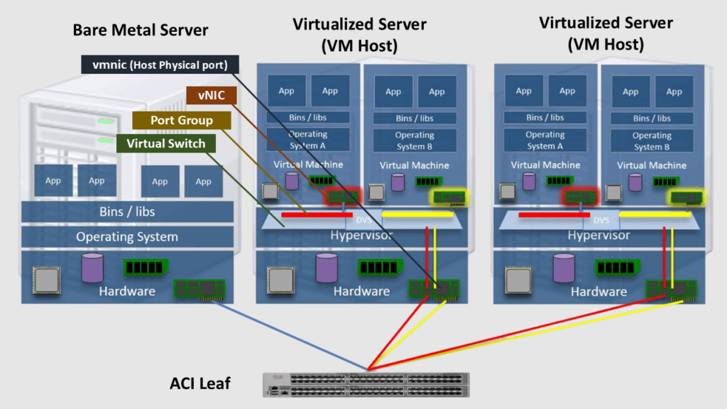
What are the Interfaces in Virtualized Servers?
As the figure below shows, Virtual machines (VMs) have Virtual Network Interface Cards (vNICs). The vNICs are logically attached to Port Groups configured in a virtual switch (vSwitch) such as the VMware vSphere Distribution Switch (VDS/DVS).
The Port Groups are essential for segmenting network traffic and ensuring that VMs connected to the same port group can communicate with each other while being isolated from VMs in different port groups. From the policy perspective, we can think about the Port Group as EPGs in ACI.
vSwitches can be logically attached to the physical NICs of the host (called vmnics) to provide external connectivity.
Cisco ACI Virtualization Overview
The Cisco ACI VMM Integration with virtualization platforms is configured at the site level, connecting a cluster of APICs with one or more clusters from VMware, Microsoft, OpenStack, Red Hat, Openshift, Rancher RKE, Nutanix, or Kubernetes.
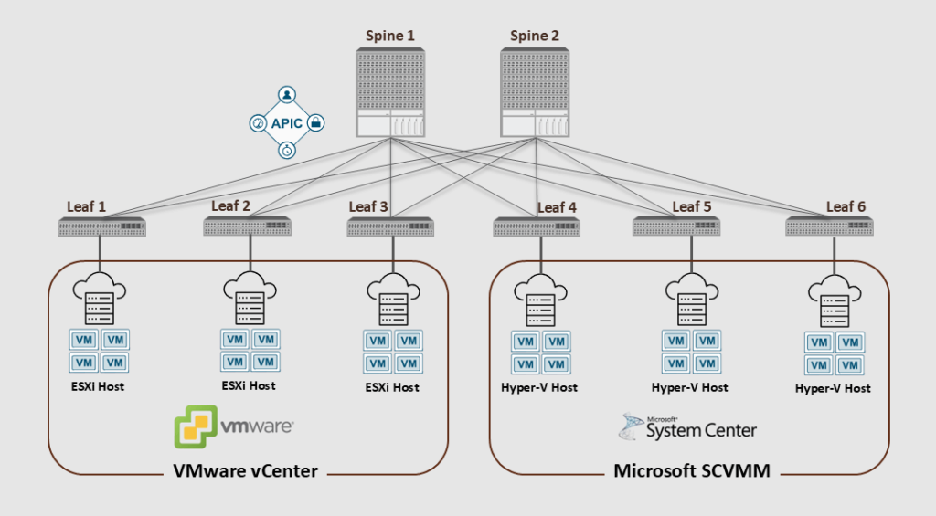
Cisco ACI can integrate with hypervisor management servers like VMware vCenter, Microsoft SCVMM, and Red Hat KVM. These hypervisor management servers, commonly referred to as Virtual Machine Managers (VMMs), enable efficient management and orchestration of virtualized environments on the site level.
The figure below shows an ACI fabric integrated with two VMM domains (VMware vCenter and Mircosoft SCVMM); each VMM domain has several hosts (ESXi & Hyper-V).
Without ACI VMM Integration
Traffic from Virtualized Servers that are not integrated with ACI will be managed as a bare-metal workload within the ACI fabric.
So, without enabling ACI Virtualization, the ACI leaf considers the traffic coming from a virtualized server as a bare-metal workload, and ACI won’t care about the VMs inside the Virtualized Server.
That means when connecting those servers to the ACI fabric, we must apply the regular access policies we typically do for a physical server (VLAN pools, physical Domain, AAEP, IPG, … etc.)
We can still classify the incoming traffic based on the encap-VLANs when it is received on the ACI leaf. However, we can’t enforce policies on the traffic between the VMs within the VM host (virtualized server); the Server Admin should do that task separately.
With ACI VMM Integration
Integrating Cisco ACI with the VMM domain provides notable advantages over handling virtual machine (VM) traffic as bare-metal. This integration enhances visibility, control, and automation within virtualized environments. Here’s a summary of the benefits:
- Simplified Management: ACI allows for the centralized management of both physical and virtual networks, reducing the complexity of managing separate environments.
- Automated Network Policies: ACI dynamically pushes network policies to the VMM, automating tasks like VLAN configuration and vSwitch settings.
- Enhanced Security: ACI provides consistent security policies across both physical and virtual environments, ensuring that security measures are uniformly applied.
- Improved Visibility: ACI offers comprehensive visibility into the network, including virtual machine traffic, which helps in monitoring and troubleshooting.
- Scalability: ACI supports scalable fault-tolerance for multiple VM controllers, making it easier to manage large-scale virtual environments.
The figure below shows that with ACI VMM integration, we can push policies between the physical and virtual workloads and within the virtualized servers.
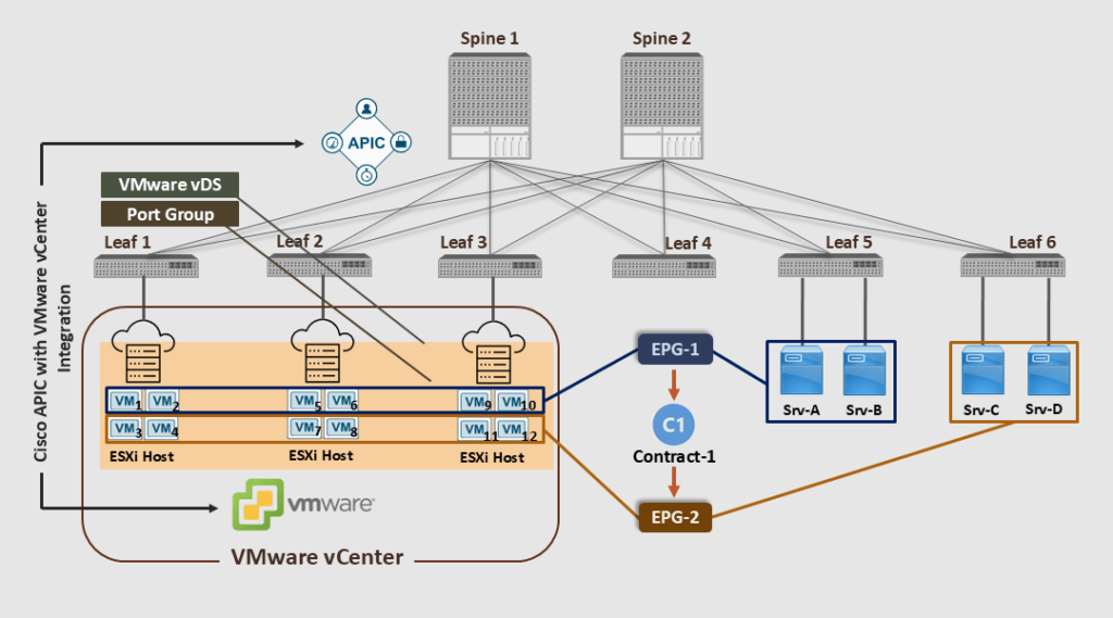
Note that Cisco APIC pushed the port groups (with same EPGs name: EPG-1 & EPG-2) to the VMware Center, and then the VMware vCenter admin assigned the VMs to the newly created Port Groups.
The ACI VMM Integration ensures that the ACI policies will be applied to the VMs for the vSwitch (vDS) internal communication with the same VM host (ESXi), between the ESXi hosts, or between the VMs and the physical servers. This happens automatically without manually deploying the access snap VLANs or other vSwitch policies.
In the above diagram, as a result of the ACI VMM Integration, VM1 can freely communicate with VM2, VM5, VM6, VM9, VM10, Srv-A, and Srv-B without a contract. On the other hand, contract-1 is deployed to restrict access to the other VMs and bare-metal servers.
Cisco ACI VMM Integration with VMware vDS Overview
The following outlines the workflow for how Cisco ACI integrates with the VMware VMM domain (VMware vCenter) and how Cisco ACI policies are pushed to the VMware virtual environment.
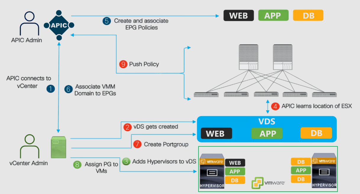
- Cisco APIC connects to VMware vCenter: The Cisco APIC admin creates the VMware VMM domain. Then, the Cisco APIC performs an initial TCP handshake with VMware vCenter specified by the VMM domain.
- The APIC creates the VMware VDS with the VMM domain name or uses an existing one if one has already been created (matching the name of the VMM domain). If we use an existing VDS, it must be inside a folder on vCenter with the same name.
- The vCenter admin adds the ESXi host to the integrated vDS and assigns the ESXi host ports as uplinks on the integrated vDS. These uplinks (vmnics) must connect to the Cisco ACI leaf switches.
- The APIC learns the location of the ESXi hosts: The Cisco APIC automatically detects the leaf interfaces that are connected to the integrated VMware vDS via the LLDP or CDP protocols.
- Create and associate EPG policies: The Cisco APIC admin creates new EPGs or reuses existing ones and associates the contract policies to them.
- Associate the VMM domain to the EPGs: The Cisco APIC admin associates the VMware VMM domain (vCenter) to the EPGs.
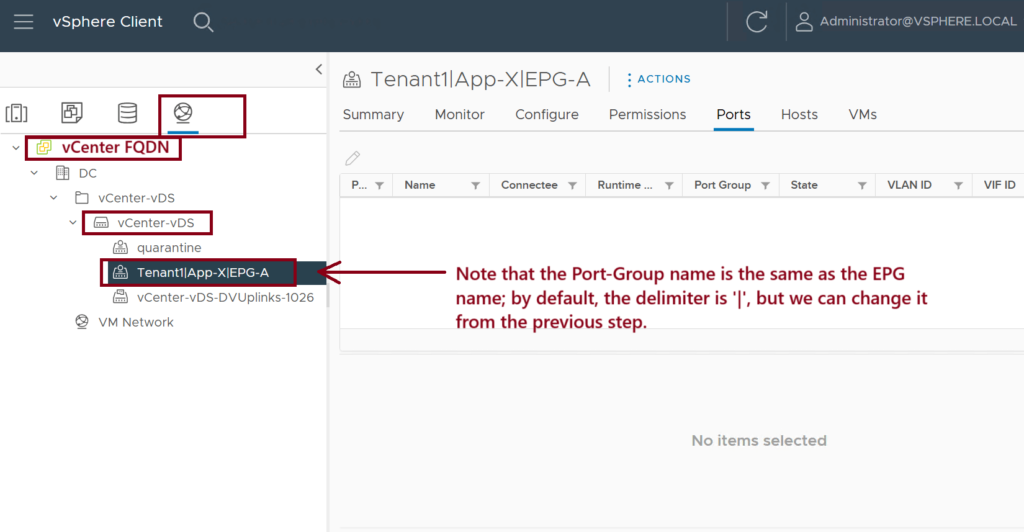
- Create Port Groups in the vDS: Cisco APIC dynamically picks a VLAN for the associated EPG and maps it to a port group in the VMware vCenter. The vCenter creates a port group with the VLAN under the integrated vDS. The port group name is a concatenation of the tenant name, the application profile name, and the EPG name (e.g., Tenant1|App-x|EPG-1).
- Assign Port Groups to VMs: The vCenter admin instantiates and assigns VMs to the newly created port groups.
- The APIC pushes policies to the leaf switches: The same VLANs dynamically mapped EPGs to port groups can then be automatically trunked over the ports where the ESXi hosts are connected; no manual VLAN trunking is required.
The result is that when a packet from the VMs comes into the ACI leaf, it will be classified into the EPG based on the encap VLAN (dynamically assigned). Then, the appropriate policies (contracts) will be applied.
ACI VMM Domain Policy Model and Components
In Cisco ACI, VMM domains enable administrators to configure connectivity policies for VM controllers. The essential components of an ACI VMM domain policy are as follows:
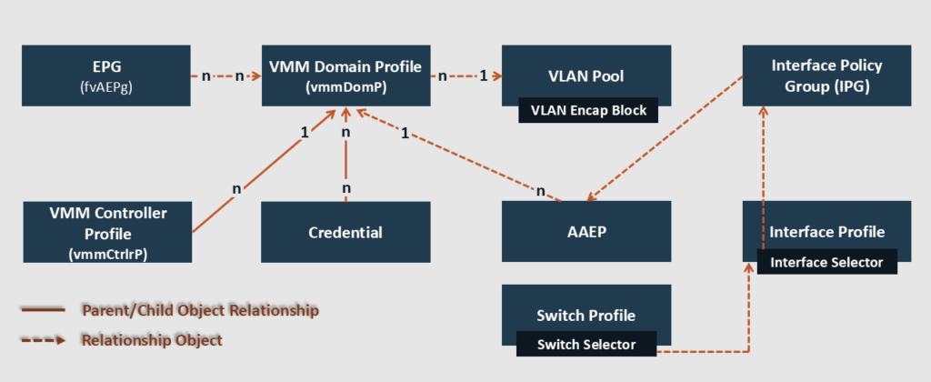
- VMM Domain Profile: A VMM domain in Cisco ACI represents a bidirectional integration between the APIC cluster and one or more VM controllers. When we define a VMM domain in ACI, the APIC will, in turn, create a virtual switch (vSwitch such as vDS) in the virtualization hosts. The VMM domain profile includes the following essential components:
- Credential: Associates a valid VM controller user credential with an APIC VMM domain. (The VM controller user should have enough privilege)
- VMM Controller: Specifies how to connect to a VM controller that is part of the VMM domain. (Like the connection to a VMware Center controller). Note that a single VMM domain can contain multiple instances of VM controllers, but they must be from the same vendor.
- EPG Association: The APIC pushes the EPGs as port groups into the VM controller.
- An EPG can span multiple VMM domains, and a VMM domain can contain multiple EPGs (n:n relationship).
- The VMM domain enables VM mobility within the same domain but not across domains.
- Attachable Entity Profile (AEP) Association: It links the VMM domain with the physical network infrastructure.
- The AEP specifies which switches and ports are available and defines which VLANs will be permitted on those host-facing interfaces.
- When a domain is mapped to an EPG, the AEP validates that the VLAN can be deployed on specific interfaces.
- VLAN Pool Association: A VLAN pool specifies the VLAN IDs or ranges used for ACI VLAN encapsulation that the VMM domain consumes.
- Only one VLAN or VXLAN pool can be assigned to a VMM domain.
- Using dynamic VLAN pools, the APIC automatically assigns VLANs to the VMM domain and dynamically allocates VLAN IDs to EPGs linked to the VMM domain.
- A fabric administrator can assign a VLAN ID statically to an EPG. However, in this case, the VLAN ID must be included in the VLAN pool with the static allocation type, or a fault will be raised.
ACI VMM Integration with VMware vDS Prerequisite
To deploy the ACI VMM Integration with VMware VDS, we’ll need to ensure the following prerequisites are met:
- The ACI Fabric should be discovered.
- The Inband/Out of Band Management should be configured.
- Connectivity between the Management interfaces on the APICs, vCenter, and ESXi hosts.
- Ensure that the versions of Cisco APIC and VMware vCenter are compatible. For detailed information, refer to the Cisco ACI Virtualization Compatibility Matrix.
- vCenter admin level credentials or the following minimum privileges (Permissions):
- Alarms.
- Distributed Switch.
- dvPort Group.
- Folder.
- Network.
- Host.
- Virtual Machine.
Cisco ACI VMM Integration with VMware vDS Configuration
The following summarizes the VMware vDS integration configuration steps:
- Set up the Access Policies for the interfaces connected to the VMware ESXi host(s).
- Configure the VMware vCenter domain (VMM). Then, confirm its vDS creation from the vCenter side.
- From the vCenter side, add the ESXi hosts to the created vDS.
- From the ACI side, assign the VMM domain to the EPGs. Then, confirm port-group creation in the vCenter.
- From the vCenter side, assign the virtual machine NIC card (vNIC) to the newly created port groups. Then, confirm the default gateway reachability and EP learning.
Referring to the figure below, let’s detail the configuration steps.
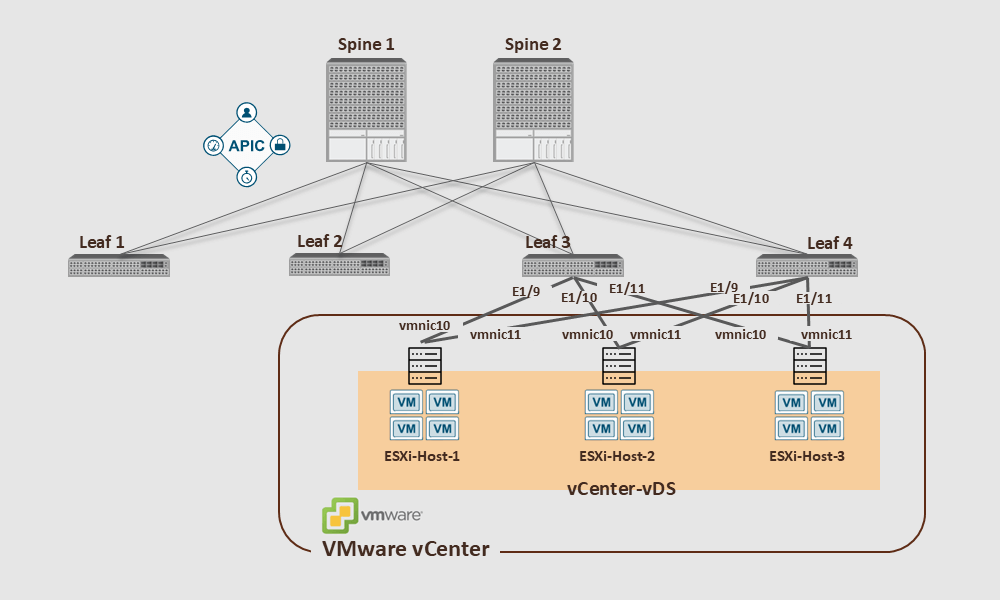
- Note that in the above example, the ESXi host interfaces are not Port-Channels, so we should consider MAC Pinning for the VM traffic. This method makes each host use the same uplink (vmnic10 or vmnic11) for each guest VM.
Step 1: Deploy the Access Policies for the Host-Connected Interfaces
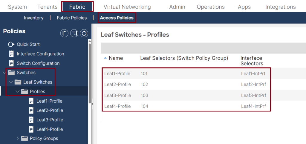
- Make sure the Switch Profiles are configured and associated with the interface profiles. ↓
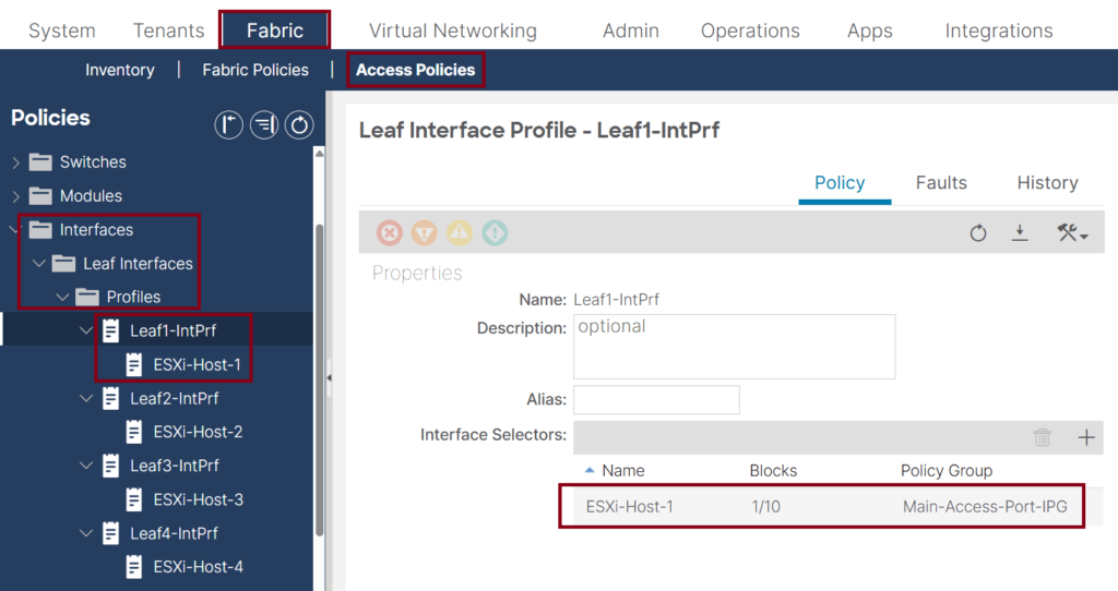
- Make sure the leaf interface profiles are configured and associated with the Interface Policy Group (IPG). ↓
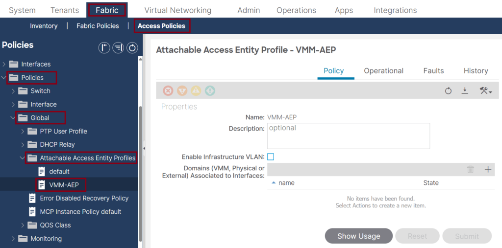
- Create an Attachable Access Entity profile (AEP) for the VMM integration usage. Note that it is recommended that a dedicated AEP be created for the ACI VMM integration. ↓
- Make sure the Interface Policy Group (IPG) has the LLDP or CDP enabled and associated with the previously created AEP that will be used with the VMM domain. ↓
- Enabling LLDP or CDP should align with the vSwitch Policy settings under the VMM domain configuration (later step).

- Ensure the VLAN pool that will be used for the VMM domain has dynamic allocation for auto VLAN assignment. ↓
![Dynamic VLAN Pool for VMM Deployment This screenshot of a Cisco ACI GUI focused on VLAN pool settings under Access Policies in the Fabric section. The VLAN Pool "VMM-VLPool" has a Dynamic Allocation showing its range set to [1001-2000], with an "External or On the Wire Encap" block.](https://learnwithsalman.com/wp-content/uploads/2025/03/Dyncamic-VLAN-Pool-for-VMM-Deployment-1024x534.png)
Step 2: Create the vCenter VMM domain
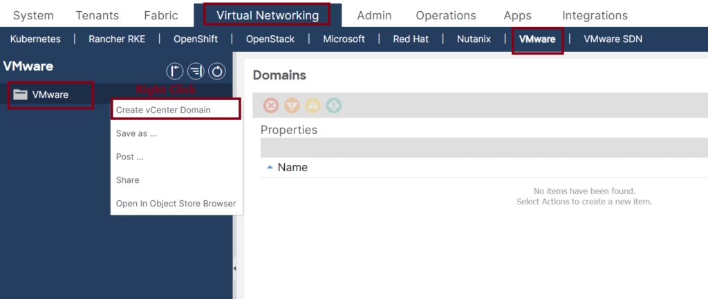
- Navigate to VMware under the Virtual Networking Tab, then create a new VMware vCenter Domain. ↓
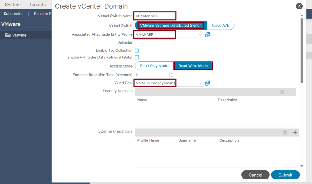
- Use the following attributes: ↓
- Name the Virtual Switch Name: vCenter-vDS.
- Ensure the Virtual Switch is set to VMware vSphere Distributed Switch (this is the default).
- In the AEP dropdown, select the VMM AEP we created earlier: VMM-AEP.
- In the VLAN Pool drop-down, select the dynamic VLAN Pool we created earlier: VMM-VLPool.
- Create a vCenter Credentials Profile that we will use to authenticate with the vCenter. ↓
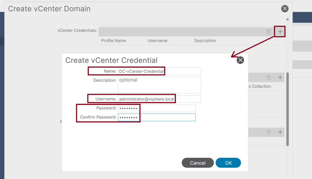
- Continue creating the VMware VMM Domain by adding the vCenter profile: ↓
- Name the vCenter Profile: DC-vCenter
- The vCenter FQDN name or IP Address
- Set the Datacenter name to: DC
- The default Mangement EPG is OOB.
- In the Associated Credential dropdown, select the previously created credential profile: DC-vCenter-Credential
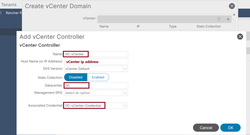
- Complete the VMware VMM Domain Setup: ↓
- Port Channel Mode: MAC Pinning+
- vSwitch Policy: CDP (we should enable CDP on both sides; we did that from the ACI side in step 1)
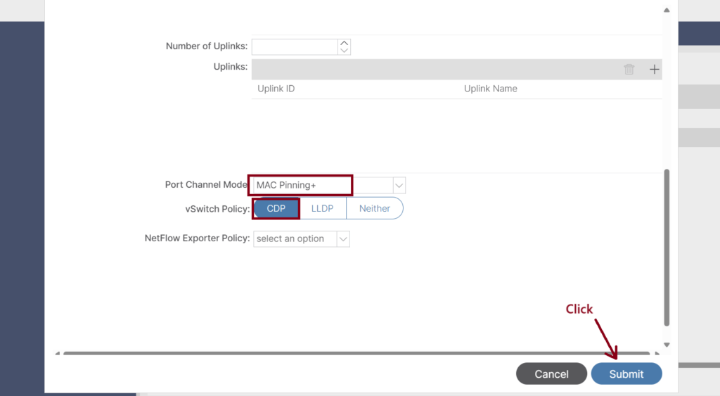
- Number of Uplinks: We can choose to associate up to 32 uplinks to the virtual switch uplink port group. This step is optional; by default, if we do not choose a value, the APIC will associate eight uplinks with the port group. We can name the uplinks after we finish creating the VMM domain. We can also configure failover for the uplinks when you create or edit the VMM domain association for an EPG.
- Port Channel Mode: The mode can be:
- Static Channel – Mode On: All static port channels (that are not running LACP) remain in this mode. The device displays an error message if we attempt to change the channel mode to active or passive before enabling LACP.
- LACP Active: LACP mode that places a port into an active negotiating state in which the port initiates negotiations with other ports by sending LACP packets.
- LACP Passive: LACP mode that places a port into a passive negotiating state in which the port responds to LACP packets that it receives but does not initiate LACP negotiation. Passive mode is useful when we do not know whether the remote system or partner supports LACP.
- MAC Pinning+: Used for pinning VM traffic in a round-robin fashion to each uplink based on the MAC address of the VM. MAC Pinning is the recommended option for channeling when connecting to upstream switches that do not support multichassis EtherChannel (MEC).
- MAC Pinning-Physical-NIC-load: Pins VM traffic in a round-robin fashion to each uplink based on the MAC address of the physical NIC.
Step 3: Confirm the vDS Creation in the vCenter
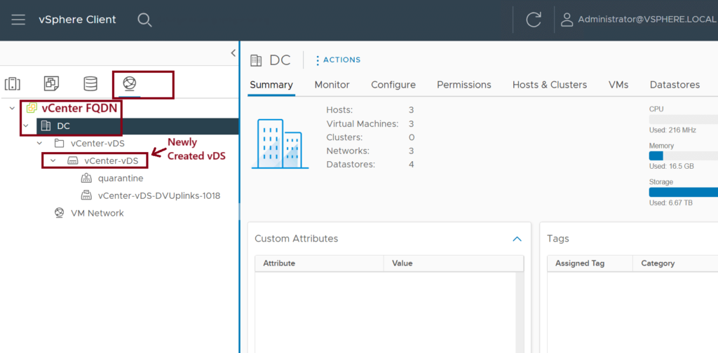
Login to the vCenter GUI and confirm the vSwitch (vCenter-vDS) creation. ↓
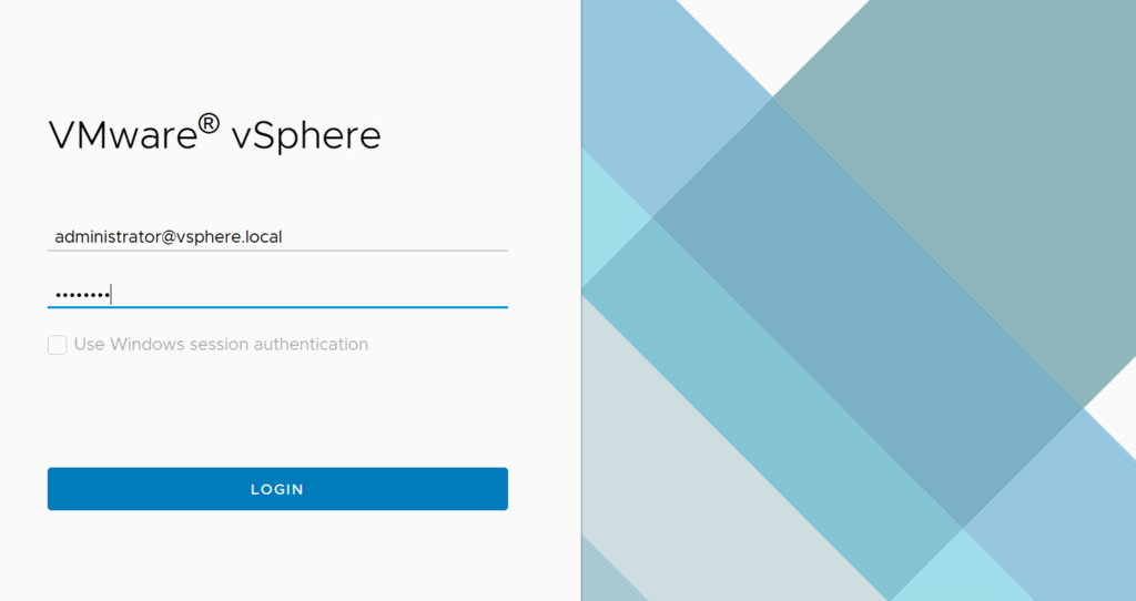
Step 4: Add the ESXi Hosts to the vDS
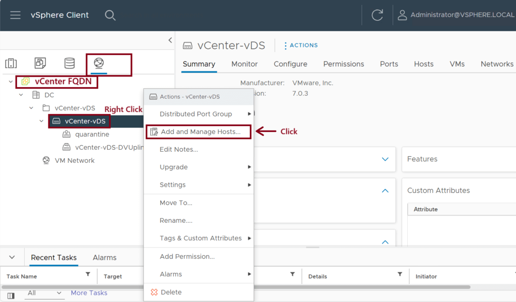
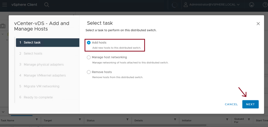
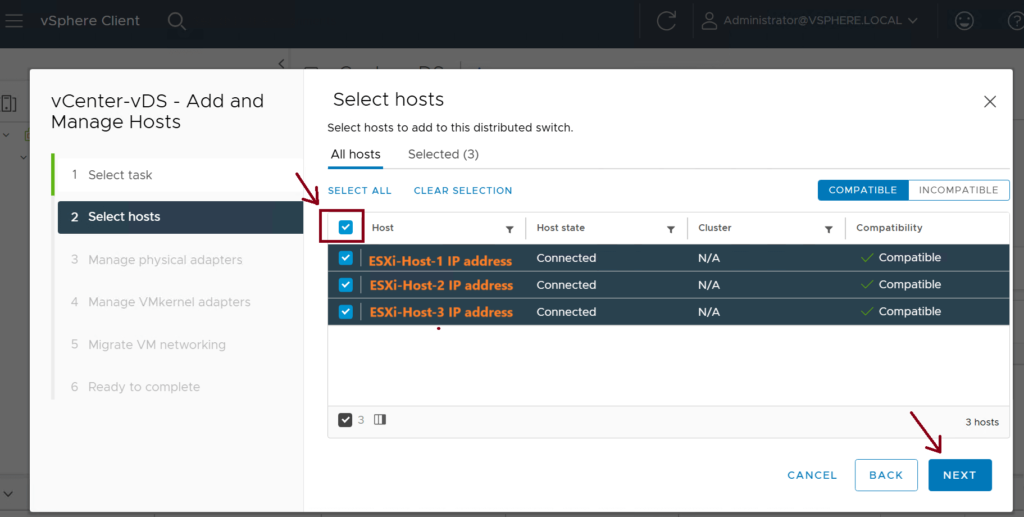
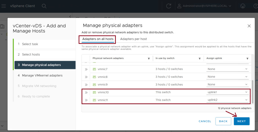
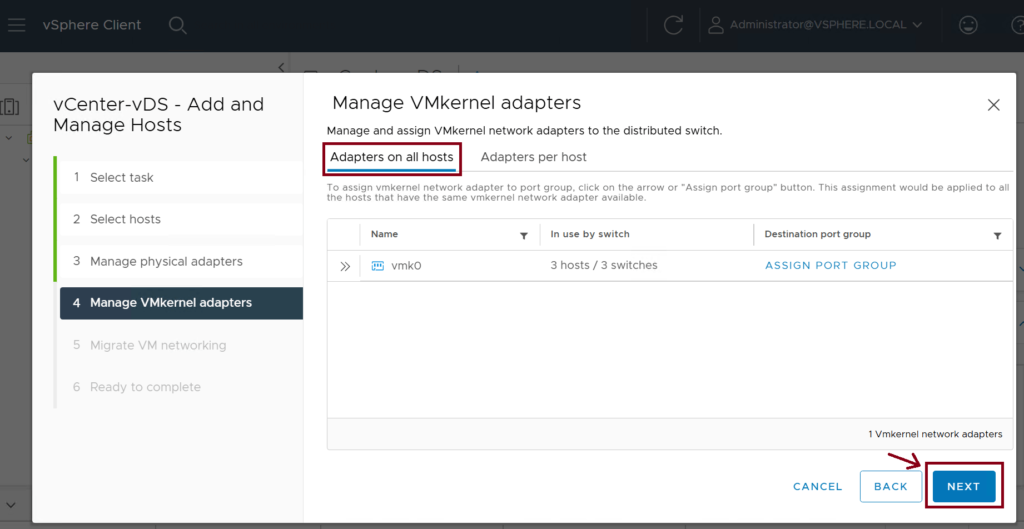
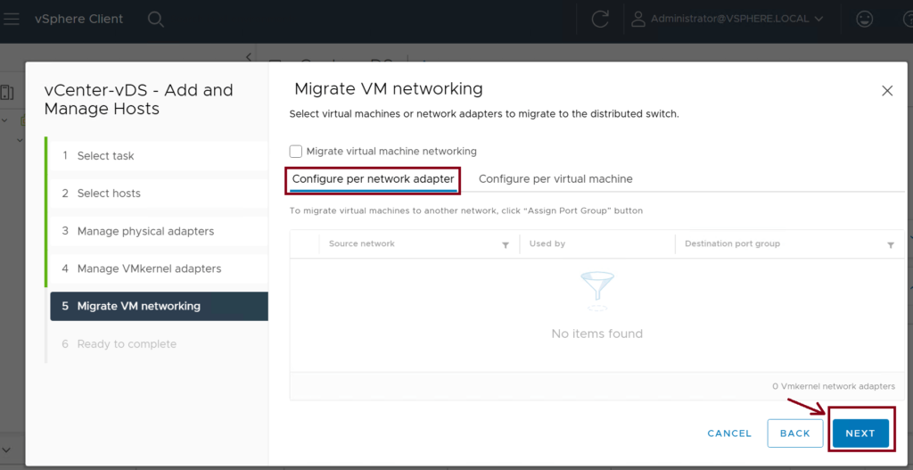
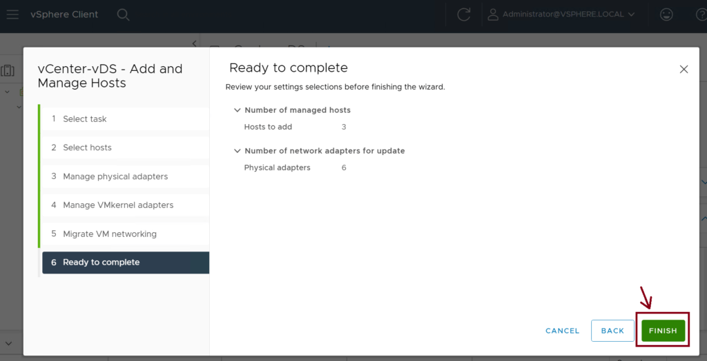
We need to associate the three ESXi hosts (ESXi-Host-1,2,3) to the newly created vDS (vCenter-vDS). Use vmnic10 and vmnic11 interfaces as uplinks to the leaf switches. ↓
Step 5: Assign the VMM domain to the EPGs
Assign the vCenter-vDS domain to the EPG(s) that you want to assign. ↓
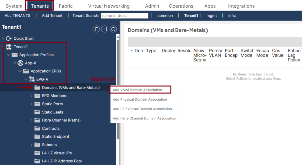
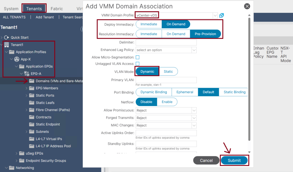
- Once the Cisco APIC has downloaded the policies to the leaf software, the Deployment Immediacy can specify when the leaf pushes the policy into the hardware policy content-addressable memory (CAM):
- Immediate: Specifies that the leaf programs the policy in the hardware policy CAM when the policy is downloaded in the leaf software.
- On Demand: Specifies that the leaf programs the policy in the hardware policy CAM only when the first packet is received through the data path; therefore, this process helps to optimize the hardware space.
- We have three possible choices for Resolution Immediacy:
- Pre-provision: VLAN will be deployed on all leaf interfaces under the AAEP associated with the VMM domain regardless of the VM controller’s hypervisor status. So, this option should be used for critical services that require VLANs to be deployed constantly instead of only dynamically when needed.
- Immediate: VLAN will be deployed on leaf interfaces only when hypervisors are detected through LLDP or CDP. Moreover, if an intermediate switch in between, such as Cisco UCS Fabric Interconnect, both leaf interface and hypervisor uplink should show the same Cisco UCS Fabric Interconnect in its CDP or LLDP information.
- On Demand: VLAN will be deployed on leaf interfaces only when hypervisors are detected, as mentioned in Immediate mode, and when at least one VM is associated with the corresponding port group. Both conditions need to be met for the VLAN to be deployed on leaf interfaces in On-Demand mode.
Step 6: Confirm the Port-Group Creation in the vDS
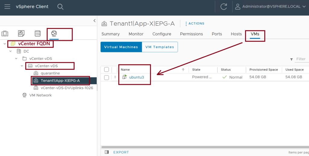
Confirm that the Tenant1|App-X|EPG-A port group exists under the vCenter-vDS vSwitch. ↓
Step 7: Assign the VM vNIC to the Port Group
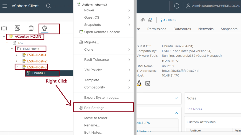
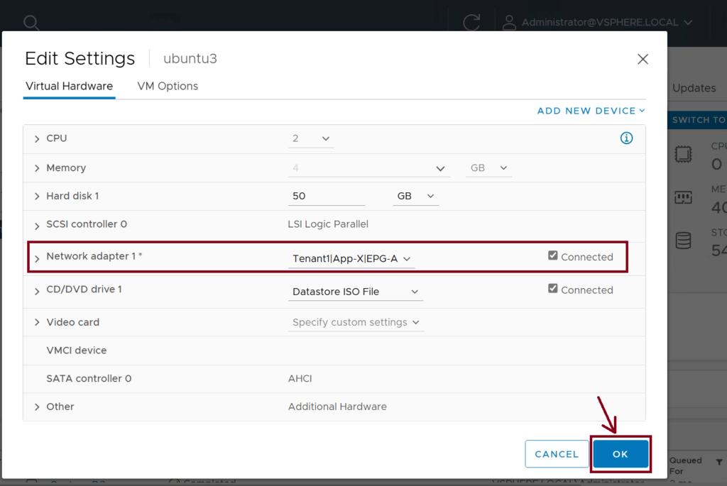
Assign the Virtual Machine vNIC to the newly created Port Group (Tenant1|App-X|EPG-A). This caused the VM (ubuntu-3) to be part of EPG-A. ↓
Step 8: Confirm the VM Reachability and Endpoint Learning
The last step is to confirm the VM (ubuntu3) reachability and endpoint learning in the VMM Domain then under the assigned EPG. ↓
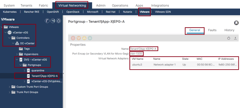
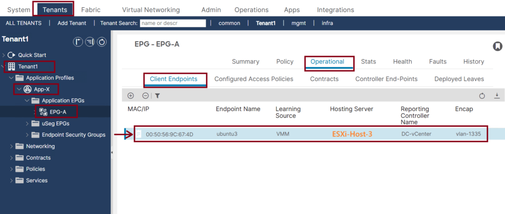
Note that the Encap VLAN-1335 is used because it is dynamically assigned from the dynamic VLAN pool that we created in step 1 with the VLAN range 1001-2000.
Now, the traffic from ubuntu3 is classified as EPG-A traffic, and we can apply the security policies (contracts) to it.
Summary
Below is the VMware vDS parameters managed by Cisco APIC:
| VMware vDS | Default Value | Configurable Using Cisco APIC Policy? |
|---|---|---|
| Name | VMM Domain name | Yes (Derived from Domain) |
| Description | ‘APIC Virtual Switch’ | No |
| Folder Name | VMM Domain name | Yes (Derived from Domain) |
| Version | Highest supported by the vCenter | Yes |
| Discovery Protocol | LLDP | Yes |
| Uplink Ports and Uplink Names | 8 | Yes |
| Uplink Name Prefix | uplink | Yes |
| Maximum MTU | 9000 | Yes |
| LACP policy | disabled | Yes |
| Port mirroring | 0 sessions | Yes |
| Alarms | 2 alarms added at the folder level | No |
Below are the VMware vDS Port Group parameters managed by Cisco APIC:
| VMware vDS Port Group | Default Value | Configurable Using Cisco APIC Policy? |
|---|---|---|
| Name | Tenant name | Application Profile Name | EPG name | Yes (Derived from EPG) |
| Port binding | Static binding | No |
| VLAN | Picked from VLAN pool | Yes |
| Load balancing algorithm | Derived based on port-channel policy on APIC | Yes |
| Promiscuous mode | Disabled | Yes |
| Forged transmit | Disabled | Yes |
| MAC change | Disabled | Yes |
| Block all ports | False | No |
Looking for Comprehensive Cisco Data Center Training?
Take your data center skills to the next level with my deep-dive courses, designed for real-world application.
Modern DC Architecture & Automation:
- Cisco Data Centers | ACI Core
- Cisco Data Centers | ACI Automation With Ansible
- Cisco Data Centers | VXLAN EVPN
Core Protocols & CCIE Prep:
Need Personalized Guidance?


Thanks for such a good guide. One question about integration: Can I connect a Virtual machine NIC to a VNI? Or at the end, we map the VLAN on the VMware side to a VNI on the ACI side? In this way, we are again limited to 4096 VLANs and cannot utilize 6 million VNI.
Hey Ehsan,
Sorry, but the question is wrong! You shouldn’t think about VNI mapping when using Cisco ACI; the APIC controls this. You can reuse the exact VLAN multiple times for several EPGs. However, you need to consider some restrictions (see: https://learnwithsalman.com/aci-vlans/).
This is a best explanation of Cisco ACI VMM Integration that I’ve ever been seen. Thanks so much for the great detailed article.
Thanks for your feedback. You’re welcome.